
USING SCIENTIFIC MOULD-MAKING TECHNIQUE TO PROVIDE YOU WELL MOULD.
Cavity/core material: 1.2344, HRC48-52
Slider material: 1.2344, HRC48-52
Surface finishing: SPI-B2
Runner system: hot runner, 1 INCOE open gate
Cycle time: 32S
Standard: DME standard
Unscrewing driving: worm
Mechanism: gear mechanism
Threaded plastic parts are commonly seen in the plastic pipe industry. There are two types of threads on the pipe: external and internal, also called male and female thread. The external threads with low accuracy are often ejected by a side core pulling mechanism. The internal thread has two structures: forced ejection and automatic unscrew.
For this mold, the thread is internal, so we need to consider the design of making forced ejection or automatic unscrew.
Three conditions that the forced ejection must follow
1. Soft glue, such as PVC, PP, and PE.
2. The tooth profile is circular, not rectangular, trapezoidal, or triangular.
3. The height of the tooth profile is small, and the following formula must be satisfied: (thread large diameter-thread small diameter) / thread small diameter ≤ A. The size of A depends on the plastic-type. Generally speaking, PP is 5%, PA is 9%, ABS is 8%, POM is 5%, LDPE is 21%, and HDPE is 6%.
Ejection system and unscrew thread mechanism
This is the most complex core structure. The automatic thread removal mechanism adopts the structure of "motor ten roller chain ten sprocket ten thread core". That is, the motor drives the roller chain, and the roller chain drives the sprocket.
During the rotation of the threaded core, the reinforcing rib on the outer surface plays a role in stopping rotation. The plastic part will move up and away from the moving model cavity in the axial direction. Finally, the bypass in the gating system is pushed by the ejector pin. The bypass is connected to the plastic part through a gate, and the plastic part is pushed out of the mold. The ejection system of this mold includes an ejector pin, an ejector fixing plate, an ejector base plate, a reset rod, and a reset spring.
The design of the side core pulling mechanism
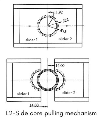
The side core pulling mechanism is the second-largest core mechanism of this kind of mold. It adopts the structure of " Huff slider + block + angle pin + locking block + positioning bead". The pressing block of the slider must adopt a mosaic structure, otherwise, it cannot be assembled.
sufficient slider stroke must be ensured to facilitate mold release. Generally, the slider stroke is added with a safety value of 1 to 5mm based on the lateral concave-convex depth. Angle pin and swing levers take smaller safety values. Other types take a larger safety value. However, when this mold uses a Huff mold (also known as a flap clamping mold) to form plastic parts such as outer patterns or coil bobbins, the lateral travel of the slider cannot simply depend on the depth of the undercut, but also on the radius of the side. In this case, the lateral stroke S of the slider can be obtained by the drawing method shown below:

The design of the temperature control system
The temperature control system of the mold directly affects the labor productivity of the mold and the molding quality of the plastic parts. Under the premise of not affecting the melt filling, try to achieve rapid cooling and balanced cooling as much as possible. The moving mold side of the mold is mainly cooled by straight-through cooling water pipes. The fixed mold side is mainly cooled by the form of "water well + water pipe".
Taizhou Saiweiyue Mould & Plastic Co., Ltd.
ADD: No.12, Jinchuan Road, Beicheng Street, Huangyan District, Taizhou City, Zhejiang Province, 318020, China
Mobile/WhatsApp: +86-15757668880
Tel/Fax: +86-0576-89888400
E-mail: [email protected]
[email protected]

Copyright © Taizhou Saiweiyue Mould & Plastic Co., Ltd. Rights Reserved. OEM/ODM Plastic Automatic Unscrew Female Thread Pipe Mould Suppliers