
USING SCIENTIFIC MOULD-MAKING TECHNIQUE TO PROVIDE YOU WELL MOULD.
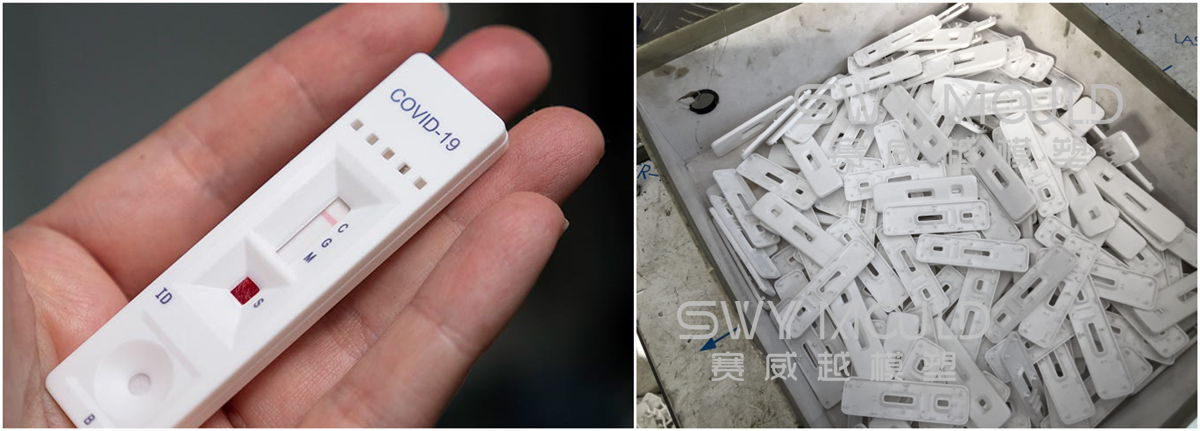
Made for at-home COVID parid test shells, there are two parts, the upper and lower two shells, made into two molds.
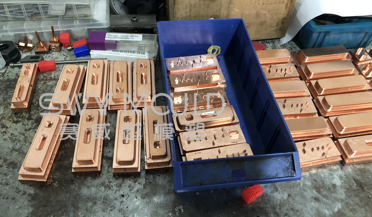
Core with beryllium copper, with a better cooling waterway to fast cycle time.
Mold cavity: 24
Mold steel: S136
Mold base: C50
Lead time: 50 days
It's unfortunate that the COVID 19 is spreading all around the world, and many people suffer from it. Some companies reach the at-home rapid COVID test, and there is a large need for this product. One customer of our SWY MOULD asked us to make the plastic injection mold of test shells.

Molding requirements of plastic at-home COVID parid test shell
As there are large demands of shell, our customers require short cycle time and long mold life. During mold design, SWY designs as many cooling ways as possible, to ensure a short cycle time. Also for the mold core, making beryllium copper to faster the cooling.
The rate of heat removal from a mold is dependent upon the thermal conductivity of the mold materials. Users of beryllium copper molds and mold inserts have reported reductions as great as 75% in total cycle times resulting from such usage. For example, the replacement of a tool steel core with a water-cooled beryllium copper core reduced the cycle time for a 152-mm injection molded cartridge case by 70%, from 3 min to 55 sec. In addition, the elimination of distortion problems with the finished part enabled molding yield to go from 75% to 99.5%. When beryllium copper is substituted for a tool or stainless steel, reductions of 30% to 50% in injection molding cycle time are not unusual.
Shorter cycle times can result in considerable savings. Using the findings above, the potential cost saving for a 6-cavity bottle mold was calculated: molding cost was 3.5 cents per bottle when using beryllium copper and 10.5 cents per bottle when using steel. The difference in raw material cost per mild was approximately $200 and the annual cost saving was $70,000. These molds are expected to produce 10 million bottles over a service life of 10 years.
Many customers said our mold quotation is very high, but you can check the mold details and mold precision, our SWY MOULD wants to provide you with effective molds at the most reasonable price. May at the beginning you need to pay a little more, but later in mass production, you can earn more back from a short cycle time and longer mold life. If you got a mold, producing only some days and break, it wastes your time and also your money. Considering all, you will know our SWY MOULD quality and service.

Design of injection mold cooling system (waterline)
1. The purpose of the cooling system
The design purpose of the cooling system is to ensure uniform cooling, as well as the shortest possible ejection time of the molded products, so as to complete the production process. The cooling design has a direct influence on product quality and the molding cycle.
2. Cooling location
* For materials that shrink a lot, such as PP, PE, and PVC, it is better that the cooling system is deployed along the shrinkage direction of products.
* On condition that the strength of mold material is guaranteed, the cooling should be close to the mold cavity or mold core surface as much as possible and evenly deployed around the molded product.
* When the mold adopts the inserting structure while the insert is big enough, it should be cooled separately. Ring-like cooling channels are often designed for circular mold inserts, such as the gear inserts. Large sliders need to be separately cooled, too. D = d + (1 – 2) (d refers to channel diameter)
* Each part of the mold has to be cooled in a uniform way. The BeCu alloy is often employed in cooling the structures that do not allow the design of a cooling system.
* When two cooling channels form an overhead crossing or are on the same level, the minimum space between them should be 3mm if the channel width is smaller than 150, and 5mm if the width is greater than 150. See the diagram.
* Cooling design should try to avoid ejector pin, ejector sleeve, ejector guide pin, lifter, ejector, screws, etc., and the smallest clearance around them should be at least 3mm. When the mold is designed with an early ejector return, the water inlet/outlet location should be able to avoid interference with it.
* If there are more than 2 sets of cooling systems in a plastic injection mold, the water inlet/outlet location should be marked with “IN” and “OUT”, which refers to Water Inlet and Water Outlet respectively. At the same time, they should be numbered to indicate the connection sequence.
3. Mold cooling channel dimension
Try to use the largest possible cooling channel, with the minimum being ø1/4’’. Accept the ø3/16” option when there are no other choices, but the largest cannot be larger than ø1/2”. The commonly used channels are sized ø1/4”, ø5/16”, and ø3/8”. Try to keep the diameter of pipes in a cooling channel as consistent as possible, so as to ensure a uniform flow rate. In a mold, there cannot be too many joints in a single set of cooling channels, so as not to affect the cooling effect.
4. Positional relationship between cooling channel and mold base
* It is preferred that water inlet/outlet are deployed along the width direction of the mold base, or 4 corner columns are needed to be added along the length direction of the mold base.
* In principle, cooling water gets in the mold from the mold base, instead of being connected to the mold interior directly. When cooling water has to get in the mold interior directly or be used to cool the sliders, a 20 – 40 clearance should be kept between the mold base and the hose nipple.
* For vertical molds, it should be avoided that the water pipes go through the clamp slots which should be at least 5mm from the cooling drilling.
* When the cooling systems of the core and cavity get in and out from the same direction, the outlets should be at least 35mm from each other.
* When the mold plate is not thick enough but cooling is needed, it should be guaranteed that the cooling center is 15mm from the top of the plate. When plate thickness measures 20mm, the distance should be kept at 13mm.
5. Cooling tower
For products designed with deep cavities, to ensure thorough cooling of product, a cooling tower should be designed. When an angle hole is needed to join 2 cooling towers, the biggest angle should be no larger than 45°, and A should be no less than 3.0mm (see the diagram). The cooling tower adopts the bronze spacer, of which the dimensions are shown below:
* 1/8″x1″x1200mm
* 1/8″x1-1/4″x1200mm
* 1/8″x1-1/2″x1200mm
Taizhou Saiweiyue Mould & Plastic Co., Ltd.
ADD: No.12, Jinchuan Road, Beicheng Street, Huangyan District, Taizhou City, Zhejiang Province, 318020, China
Mobile/WhatsApp: +86-15757668880
Tel/Fax: +86-0576-89888400
E-mail: [email protected]
[email protected]

Copyright © Taizhou Saiweiyue Mould & Plastic Co., Ltd. Rights Reserved. OEM/ODM Plastic Shell Molding Of At-home COVID Rapid Test Suppliers